The Moment Distance Index or MDI is a shape-based metric that is calculated with a matrix of distances. So far, MDI was used to analyze the spectral regions of chlorophyll and carotenoids to separate maize from soybean and other advance spectral analysis for vegetation studies.
Since MDI looks at the shape of the curve, it was used to exploit the spectral bands of Landsat for mapping sparse vegetation. More recently, MDI was utilized in an object-based image analysis (OBIA) and came out a very important variable for mapping summer vegetation and even greenhouses.
The application of MDI on shape analysis can be many. Recently, we applied MDI to LiDAR waveforms. Our results using LVIS dataset showed a promise.
So how can you compute the Moment Distance Index? See the steps below as I explain the Moment Distance (MD) framework.
I used here as as example, a reflectance curve. Note that you can simply replace the reflectance curve by any other types of curves, as MDI is a shape index.
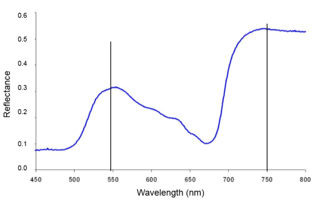
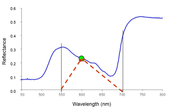
This is a typical vegetation reflectance curve.
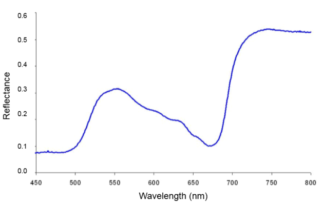
1. Pick pivots points, one on the left (LP) and one on the right (RP). The pivots set the boundary of the analysis. They can be placed anywhere. If you want to concentrate to a specific wavelength range, then establish your LP and RP in that range. Also, if you cannot decide where to place the pivots, just put one (LP) at the very first wavelength (e.g. 450 nm) and the other (RP) at the very end (e.g. 800 nm). In this example, I picked LP at 550 nm and the RP at 750 nm.
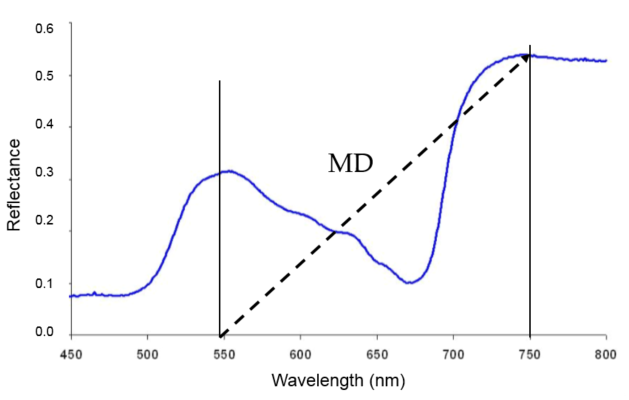
2. Start computing Moment Distances (MDs). The diagonal line you see below is an example of MD. It goes from 550 nm to a point on the curve located at 750 nm. The distance (or length) of this MD line can be computed using Pythagorean theorem.
MD = sqrt [(reflectance at 750nm)^2 + (750 – 550)^2]
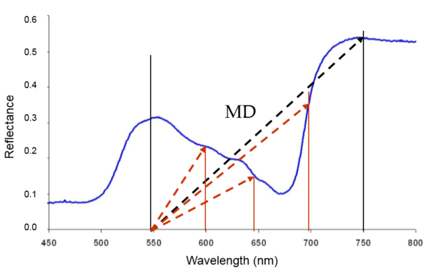
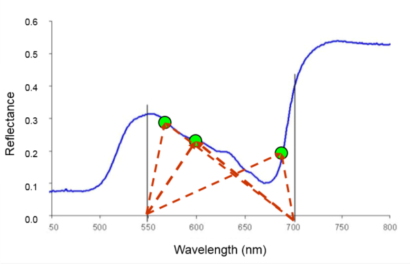
3. You’ve just computed one MD! You can compute for more. As you see below, I can compute other MDs — for a point on the curve located at 600 nm, for a point at 650 nm, and for a point at 700 nm. In this illustration alone, I already have 4 MDs (or distances of points on the curve from the 550 nm pivot).
Imagine if there would be more bands in between pivots 550 and 750 nm! Imagine a hyperspectral curve and the number of MDs you could compute!
Note: How will this be beneficial? Well, looking at the distance of a point on the curve from a reference point on the x-axis gives you an idea of the form of the curve from a point of perspective. The more points are considered, the more the curve is defined.
4. Now, if I can define a point on the curve by an MD from the LP (550 nm), I can also define the MD of the same point, but this time from the RP (700 nm).
5. With that, I can also compute the MDs for all points on the curve from the RP (700 nm).
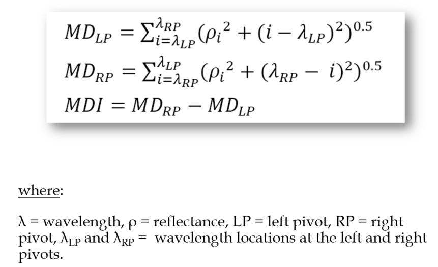
6. After step 5, I now have two sets of MDs. One set is composed of MDs from the LP and the other set is from the RP. I would take the sum of all MDs from LP and record this MD(LP). I’d do the same for MDs from RP and record this MD(RP). These are the final MD equations:
7. The Moment Distance Index (MDI) is simply the difference between the MD(RP) and the MD(LP).
That’s it! That’s basically are the steps to computing MDI. At the initial tests, I used Excel to hasten the process. Believe me it is easy, once the equations are set up.
What we have observed so far:
- Moment distance is sensitive to wavelength shifting (from the point of perspective.) You will know that a point on the curve (vis-à-vis another curve) has shifted to another wavelength through analyzing the MD.
- Since it is a distance-based method with emphasis on the curve structure, it detects the behavior of the curve — even if a curve looks identical with another one.
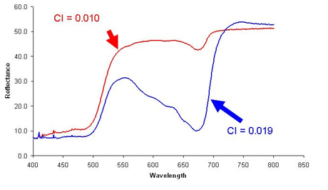
Take this example of two different reflectance curves and the values of the Chlorophyll Index (CI). The CI came out almost the same!
I then computed MDI within the red-edge region (720 to 730 nm).
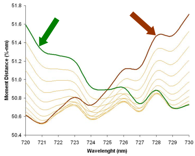
Below shows MD values as computed from LP (720 nm; brown line) and as computed from RP (730 nm; green line). This graph is for the red curve above with CI = 0.010.
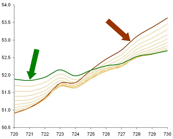
Now, here’s the graph for the blue curve above with CI = 0.019.
See the differences? While CI barely detects differences, the MDI shows huge differences between curves. In fact, the MDI for the red curve is only 0.00733, while for the blue curve, the MDI is 0.05199!
I will be posting more test results of the MDI soon. If you have questions, let me know through the comment section below.
Cheers everyone!
UPDATE: For those using ENVI, use this equation for Landsat 8 through “Band Math” tool. b1 to b7 represent the 7 bands of Landsat 8 utilized to compute MDI.
((ulong(b1) + ulong(sqrt(b2^2+0.04^2)) + ulong(sqrt(b3^2+0.12^2)) + ulong(sqrt(b4^2+0.21^2)) + ulong(sqrt(b5^2+0.43^2)) + ulong(sqrt(b6^2+1.17^2)) + ulong(sqrt(b7^2+1.76^2)))) – ((ulong(b7) + ulong(sqrt(b6^2+1.04^2)) + ulong(sqrt(b5^2+1.33^2)) + ulong(sqrt(b4^2+1.55^2)) + ulong(sqrt(b3^2+1.64^2)) + ulong(sqrt(b2^2+1.72^2)) + ulong(sqrt(b1^2+1.76^2))))
